2. Model Code and Configuration Description
This chapter presents the technical description of the WRF-Hydro model code. The chapter is divided into the following sections:
2.1 Brief Code Overview
WRF-Hydro is written in a modularized, modern Fortran coding structure whose routing physics modules are switch-activated through a model namelist file called hydro.namelist. The code has been parallelized for execution on high-performance, parallel computing architectures including Linux operating system commodity clusters and multi-processor desktops as well as multiple supercomputers. More detailed model requirements depend on the choice of model driver, described in the next section.
2.2 Driver Level Description
WRF-Hydro is essentially a group of modules and functions which handle the communication of information between atmosphere components (such as WRF, CESM or prescribed meteorological analyses) and sets of land surface hydrology components. From a coding perspective the WRF-hydro system can be called from an existing architecture such as the WRF model, the CESM, NASA LIS, etc. or can run in a standalone mode with its own driver which has adapted part of the NCAR High Resolution Land Data Assimilation System (HRLDAS). Each new coupling effort requires some basic modifications to a general set of functions to manage the coupling. In WRF-Hydro, each new system that WRF-Hydro is coupled into gets assigned to a directory indicating the name of the coupling component WRF-Hydro is coupled to. For instance, the code which handles the coupling to the WRF model is contained in the WRF_cpl/ directory in the WRF-Hydro system. Similarly, the code which handles the coupling to the offline Noah land surface modeling system is contained within the Noah_cpl/ directory and so on. Description of each directory is provided in 2.4 Directory Structures.
The coupling structure is illustrated here, briefly, in terms of the coupling of WRF-Hydro into the WRF model. A similar approach is used for coupling the WRF-Hydro extension package into other modeling systems or for coupling other modeling systems into WRF-Hydro.
Example: For coupled WRF/WRF-Hydro runs the WRF-Hydro components are compiled as a single library function call with the WRF system. As such, a single executable is created upon compilation (wrf.exe). As illustrated in Figure 2.1, WRF-hydro is called directly from WRF in the WRF surface driver module (phys/module_surface_driver.F90). The code that manages the communication is the WRF_drv_Hydro.F90 interface module that is contained within the WRF_cpl/ directory. The WRF_drv_Hydro.F90 interface module is the specific instance of a ‘General WRF-Hydro Coupling Interface’ for the WRF model which passes data, grid and time information between WRF and WRF-Hydro. Components within WRF-Hydro then manage the dynamic regridding “data mapping” and sub-component routing functions (e.g. surface, subsurface and/or channel routing) within WRF-Hydro (see Fig. 1.1 for an illustration of components contained within WRF-Hydro).
Upon completion of the user-specified routing functions, WRF-Hydro will remap the data back to the WRF model grid and then pass the necessary variables back to the WRF model through the WRF_drv_Hydro.F90 interface module. Therefore, the key component of the WRF-Hydro system is the proper construction of the WRF_cpl_Hydro interface module (or more generally {XXX}_cpl_Hydro). Users wishing to couple new modules to WRF-Hydro will need to create a unique “General WRF-Hydro Coupling Interface” for their components. Some additional examples of this interface module are available upon request for users to build new coupling components. This simple coupling interface is similar in structure to other general model coupling interfaces such as those within the Earth System Modeling Framework (ESMF) or the Community Surface Dynamics Modeling System (CSDMS).
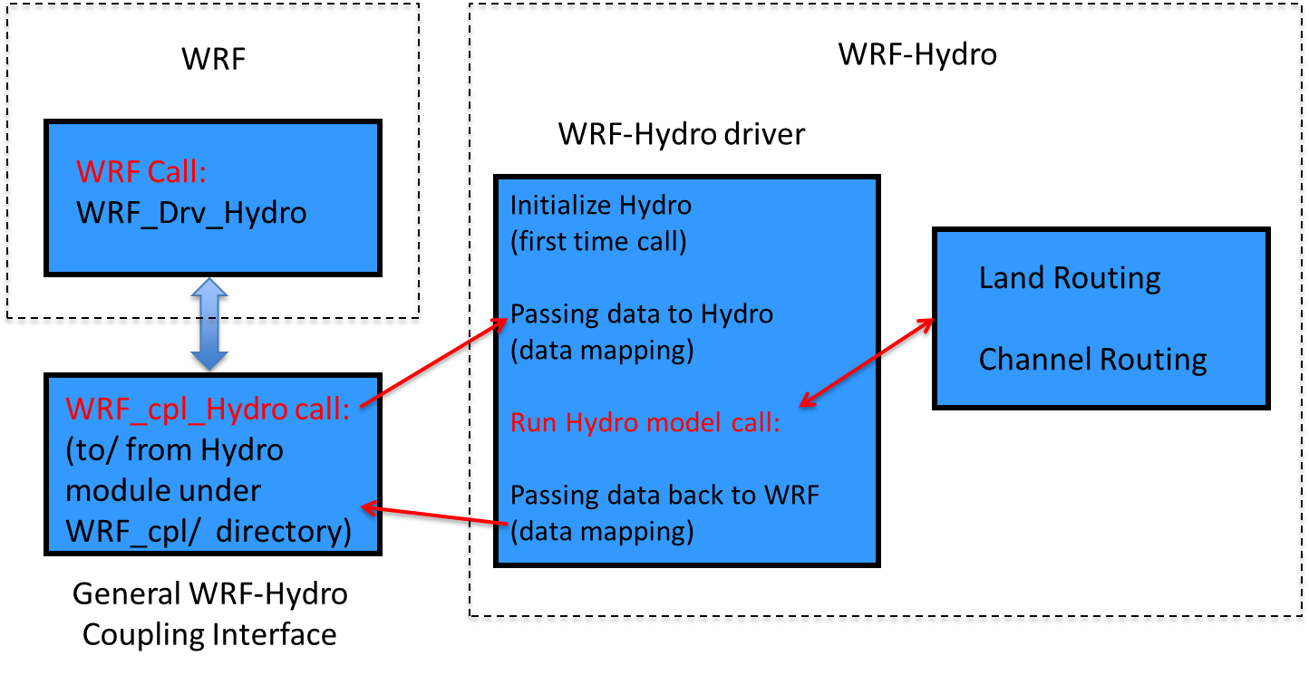
Figure 2.1 Schematic illustrating the coupling and calling structure of WRF-Hydro from the WRF Model.
The model code has been compiled using the Intel ifort compiler and
the freely-available GNU Fortran compiler gfortran for use with
Unix-type operating systems on desktops, clusters, and supercomputing
systems. Because the WRF-Hydro modeling system relies on netCDF input and
output file conventions, netCDF Fortran libraries must be installed and
properly compiled on the system upon which WRF-Hydro is to be executed.
Not doing so will result in numerous error messages such as *…undefined
reference to netCDF library …* or similar messages upon compilation.
For further installation requirements see the FAQs page of the website
as well asin the How To Build & Run WRF-Hydro v5 in Standalone Mode document
also available from https://ral.ucar.edu/projects/wrf_hydro.
2.3 Parallelization strategy
Parallelization of the WRF-Hydro code utilizes geographic domain decomposition and ‘halo’ array passing structures similar to those used in the WRF atmospheric model (Figures 2.2 and 2.3). Message passing between processors is accomplished using MPI protocols. Therefore the relevant MPI libraries must be installed and properly compiled on the system upon which WRF-Hydro is to be executed in parallel mode. Currently sequential compile is not supported so MPI libraries are required even if running over a single core.

Figure 2.2 Schematic of parallel domain decomposition scheme in WRF-Hydro. Boundary or ‘halo’ arrays in which memory is shared between processors (P1 and P2) are shaded in purple.
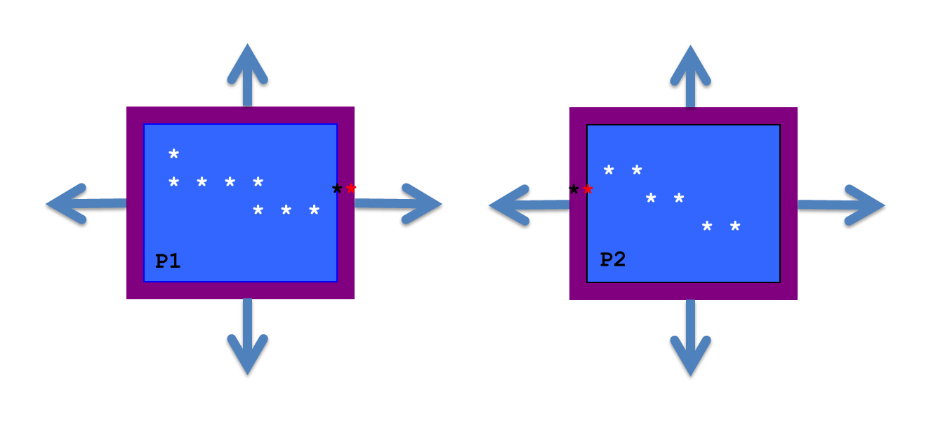
Figure 2.3 Schematic of parallel domain decomposition scheme in WRF-Hydro as applied to channel routing. Channel elements (stars) are communicated at boundaries via ‘halo’ arrays in which memory is shared between processors (P1 and P2). Black and red stars indicate overlapping channel elements used in the diffusive wave solver.
2.4 Directory Structures
The top-level directory structure of the code is provided below as nested under the wrf_hydro_nwm_public root directory and the subdirectory structures are described thereafter. The tables below provide brief descriptions of the file contents of each directory where the model code resides.
File/directory name |
Description |
|---|---|
Main code files and directories (under version control in a GitHub repository): |
|
Top-Level Files and Directories: |
|
CMakeLists.txt |
Top-level CMake build script used to compile the WRF-Hydro model |
docs/ |
Pointer to location of full documentation (i.e. this document). |
tests/ |
Scripts and data used to test the model |
src/ |
WRF-Hydro Model source code |
Source code directories under `src/`: |
|
CPL/Noah_cpl/ |
Contains the WRF-Hydro coupling interface for coupling WRF-Hydro components with the standalone (offline) Noah land surface model data assimilation and forecasting system |
CPL/NoahMP_cpl/ |
Contains the WRF-Hydro coupling interface for coupling WRF-Hydro components with the standalone (offline) Noah-MP land surface model data assimilation and forecasting system |
CPL/WRF_cpl/ |
Contains the WRF-Hydro coupling interface for coupling WRF-Hydro components with the WRF system |
CPL/CLM_cpl/ , CPL/LIS_cpl/ , CPL/NUOPC_cpl/ |
Work in progress for ongoing coupling work. Only NUOPC is actively supported. |
Data_Rec/ |
Contains some data declaration modules |
Debug_Utilities/ |
Utilities for debugging |
deprecated/ |
Contains files not currently used |
HYDRO_drv/ |
Contains the high-level WRF-Hydro component driver: module_HYDRO_drv.F90 |
Land_models/Noah/ |
Contains the Noah land surface model driver for standalone or uncoupled applications |
Land_models/NoahMP/ |
Contains the Noah-MP land surface model driver for standalone or uncoupled applications |
MPP/ |
Contains MPI parallelization routines and functions |
nudging/ |
Contains nudging data assimilation routines and functions |
Rapid_routing/ |
Contains the files necessary for RAPID routing model coupling. Unsupported as version of RAPID is out of date. |
Routing/ |
Contains modules and drivers related to specific routing processes in WRF-Hydro |
template/ |
Contains example namelist files for Noah, Noah-MP and the WRF-Hydro modules (HYDRO). Default and example parameter tables are also included for HYDRO. Note: Parameter tables for Noah and Noah-MP are stored within the Land_models directory. |
utils/ |
internal model versioning |
Files: |
|
docs/BUILD.md |
WRF-Hydro build instructions for the standalone model |
wrf_hydro_config |
Configure script for coupled WRF | WRF-Hydro configuration |
*.json |
JSON files used for testing |
Local files and directories created by CMake in the build directory (not part of the version controlled repository): |
|
Directories: |
|
lib/ |
Directory where compiled libraries are written |
mods/ |
Directory where compiled .mod` files are written upon compilation |
Run/ |
Directory where model executable, example parameter tables, and example namelist files for the compiled model configuration will be populated. These files will be overwritten on compile. It is recommended the user copy the contents of this directory into an alternate location, separate from the code, to execute model runs. |
File/directory name |
Description |
|---|---|
Overland/ |
Directory containing overland routing modules |
Makefile |
Makefile for WRF-Hydro component |
module_channel_routing.F90 |
Module containing WRF-Hydro channel routing components |
module_date_utilities_rt.F90 |
Module containing various date/time utilities for routing routines |
module_GW_baseflow.F90 |
Module containing model physics for simple baseflow model |
module_HYDRO_io.F90 |
Module containing WRF-Hydro input and (some) output functions |
module_HYDRO_utils.F90 |
Module containing several WRF-Hydro utilities |
module_lsm_forcing.F90 |
Module containing the options for reading in different forcing data types |
module_noah_chan_param_init_rt.F90 |
Module containing routines to initialize WRF-Hydro routing grids |
module_NWM_io.F90 |
Module containing output routines to produce CF-compliant desired output files. |
module_NWM_io_dict.F90 |
Dictionary to support CF-compliant output routines. |
module_RT.F90 |
Module containing the calls to all the WRF-Hydro routing initialization |
module_UDMAP.F90 |
Module for the user-defined mapping capabilities, currently used for NWM configuration (NHDPlus network) |
Noah_distr_routing.F90 |
Module containing overland flow and subsurface physics routines and grid disaggregation routine |
module_gw_gw2d.F90 |
Module containing routines for the experimental 2D groundwater model |
2.5 Model Sequence of Operations
The basic structure and sequencing of WRF-Hydro are diagrammatically illustrated in Figure 2.4 management, initialization, I/O and model completion) is handled by the WRF-Hydro system unless WRF-Hydro is coupled into, and beneath, a different modeling architecture. The WRF-Hydro system can either call an independent land model driver such as the NCAR High Resolution Land Data Assimilation System (HRLDAS) for both Noah and Noah-MP land surface models to execute column land surface physics or be called by a different modeling architecture such as WRF, the NCAR CESM, or the NASA LIS. When run in a standalone or “uncoupled” mode, WRF-Hydro must read in the meteorological forcing data necessary to perform land surfac model calculations and it contains the necessary routines to do this. When run in a coupled mode with WRF or another larger architecture, WRF-Hydro receives meteorological forcing or land surface states and fluxes from the parent architecture. The basic execution process is as follows:
Upon initialization static land surface physiographic data are read into the WRF-Hydro system and the model domain and computational arrays are established.
Depending on whether or not WRF-Hydro is run offline as a standalone system or whether it is coupled into another architecture, either forcing data is read in or land surface states and fluxes are passed in.
For offline simulations which require land model execution, the gridded column land surface model is executed.
If routing is activated and there is a difference between the land model grid and the routing grid, land surface states and fluxes are then disaggregated to the high-resolution terrain routing grids.
If activated, sub-surface routing physics are executed.
If activated, surface routing physics are executed.
If activated, the conceptual base flow model is executed.
If activated, channel and reservoir routing components are executed. Streamflow nudging is currently available to be applied within the Muskingum-Cunge routing call.
Updated land surface states and fluxes are then aggregated from the high-resolution terrain routing grid to the land surface model grid (if routing is activated and there is a difference between the land model grid and the routing grid).
Results from these integrations are then written to the model output files and restart files or, in the case of a coupled WRF/WRF-Hydro simulation, passed back to the WRF model.
As illustrated at the bottom of the Figure 2.4 component with NCAR’s DART (https://www.image.ucar.edu/DAReS/DART/) has been developed. This currently only works with WRF-Hydro in standalone mode. DART updates WRF-Hydro states independently of model time integration.

Figure 2.4 Modular calling structure of WRF-Hydro.
2.6 WRF-Hydro compile-time options
Compile time options are choices about the model structure which are determined when the model is compiled. Compile time choices select a WRF-Hydro instance from some of the options illustrated in Figure 2.4. Compile time options fall into two categories: 1) the selected model driver, and 2) the compile options for the choice of driver. In this guide we limit the description of model drivers to WRF, Noah, and Noah-MP. Configuring, compiling, and running WRF-Hydro in standalone mode is described in detail in the How To Build & Run WRF-Hydro V5 in Standalone Mode document available from https://ral.ucar.edu/projects/wrf_hydro.
Compile-time options are listed during the CMake build configuration
process. These options are passed to CMake as environment variables
using -D[OPTION]=[0|1] syntax. Those options/variables are listed
below along with a description of what each option does:
===================================================================
-- Start of WRF-Hydro Env VARIABLES
WRF_HYDRO = 1                        Always set to 1 for WRF-Hydro

HYDRO_D = 0                Set to 1 for enhanced diagnostic output

WRF_HYDRO_RAPID = 0         Currently unsupported, always set to 0

SPATIAL_SOIL = 1               Set to 1 to allow NoahMP LSM to use
                                 spatially distrubuted parameteter
                               vs. a table based on soil class and
                                               land use categories

WRFIO_NCD_LARGE_FILE_SUPPORT = 0               Set to 1 if using a
                                       WRF/WRF-Hydro coupled build

NCEP_WCOSS = 0                  Set to 1 if compile for NOAA WCOSS

NWM_META = 0        Set to 1 if using NWM-style metadata in output

WRF_HYDRO_NUDGING = 0         Set to 1 if using streamflow nudging

OUTPUT_CHAN_CONN = 0            Set to 1 to output channel network
                                            diagnostic information

PRECIP_DOUBLE = 0                  Set to 1 to double all incoming
                           precipitation (for debug purposes only)

WRF_HYDRO_NUOPC = 0             Set to 1 when using NUOPC coupling
===================================================================
2.7 WRF-Hydro run time options
There are two namelist files that users must edit in order to successfully execute the WRF-Hydro system in a standalone mode or “uncoupled” to WRF. One of these namelist files is the hydro.namelist file and in it are the various settings for operating all of the routing components of the WRF-Hydro system. The hydro.namelist file is internally commented so that it should be clear as to what is needed for each setting. A full annotated example of the hydro.namelist file is provided in A6. WRF-Hydro hydro.namelist File with Description of Options.
The second namelist is the namelist which specifies the land surface model options to be used. This namelist can change depending on which land model is to be used in conjunction with the WRF-Hydro routing components. For example, a user would use one namelist when running the Noah land surface model coupled to WRF-Hydro but that user would need to use a different namelist file when running the CLM model, the Noah-MP model or NASA LIS model coupled to WRF-Hydro. The reason for this is WRF-Hydro is intended to be minimally-invasive to other land surface models or land model driver structures and not require significant changes to those systems. This minimal invasiveness facilitates easier coupling with new systems and helps facilitate easy supportability and version control with those systems. When the standalone WRF-Hydro model is compiled the appropriate namelist.hrldas template file is copied over to the Run directory based upon the specified land surface model.
In WRF-Hydro v5.4, Noah and Noah-MP land surface models are the main land surface model options when WRF-Hydro is run in standalone mode. Both Noah and Noah-MP use a namelist file called namelist.hrldas, which, as noted above, will contain different settings for the two different land surface models. For a run where WRF-Hydro is coupled to the WRF model, the WRF model input file namelist.input becomes the second namelist file. Full annotated example namelist.hrldas files for Noah and Noah-MP are provided in A4. Noah namelist.hrldas File with Description of Options and A5. Noah-MP namelist.hrldas File with Description of Options.
2.8 Build Instructions
Requirements
Compiler |
Version |
|---|---|
GNU |
7.4+ |
Intel |
2018+ |
NVidia/PGI |
20.4+ |
Cray |
8+ |
Libraries/Software |
Version |
|---|---|
MPI |
3.x+ |
Fortran NetCDF |
4.4+ |
CMake |
3.12+ |
Install dependencies for Debain/Ubuntu
$ apt install -y git cmake libnetcdff-dev mpi-default-dev
Install/activate dependencies for Red Hat/Fedora
$ dnf install -y git cmake netcdf-fortran-mpich-devel
<log out and back in to activate environment modules>
$ module load mpi
CMake Build
$ mkdir build
$ cd build
$ cmake ..
$ make -j 4
The executables, namelists and tables are now in the build/Run directory.
Testcases with domain setups can be found here.
To build with additional functionality, enter cmake .. -DFOO=1 where the
available options are described in the following table.
CMake WRF-Hydro Specific Options |
Functionality |
|---|---|
|
Default: turn on WRF-Hydro |
|
Enhanced diagnostic output for debugging |
|
Spatially distributed parameters for NoahMP |
|
Enable the streamflow nudging routines for Muskingum-Cunge Routing |
|
Output NWM Metadata |
|
For gridded channel routing, write the channel connectivity to a netcdf file |
|
Double precipitation from hydro forcing |
|
Do not use unless working on the WCOSS machines |
Unsupported Functionality |
|
|---|---|
|
Coupling with NUOPC, this option is not currently supported |
|
Coupling with the RAPID routing model, this option is not currently supported |
CMake Testcase
To download and setup the Croton testcase in build/Run use one of the
following commands.
The first time the croton.tar.gz file will be downloaded, extracted, and configured.
Future commands will reconfigure the Run directory.
Make Command |
|---|
make croton |
make croton-gridded |
make croton-gridded-no-lakes |
make croton-nwm |
make croton-nwm_ana |
make croton-nwm_longe_range |
make croton-reach |
make croton-reach-lakes |